Clayton Lennartz
July 29, 2023
I’m getting ready to start the engine for the first time and want to double check a couple of things before I do.
For some reason, I thought that the mix for first tank of fuel should be 30:1 and then 40:1 for all future tanks. However, now that I’m ready to start the engine, I can’t find that in the documentation. What’s the correct mix for the first tank of fuel?
I was planning to start the engine for a few minutes to make sure everything works. Then shut it down, finish the clean up (seal wire feedthrus, install gloveboxes, install skirts, etc.) and start testing it. However, the manual says that it should be run for an nearly 2 hours minutes for break in (2500 RPM for 20 minutes, Idle to cool, 3000 RPM for 20 minutes, idle to cool, 3500 RPM for 20 minutes, idle to cool, 4000 RPM for 20 minutes, idle to cool). I was also planning to do the first run (a few minute flight) at a flat field (easier to recover if there’s an issue). Basically my plan was: Start the engine for 5 minutes to make sure it works; finish all the clean up tasks; run it in a field for 15-30 minutes to make sure it all flies correctly, then take it to the water for break in. What’s your thoughts on the initial startup?
Please advise.
Answer:
Always use 40:1 fuel oil mixture. The confusion in the manual is because we incorporated parts of Hirth's manual which does state 30:1 for break-in but we have always used 40:1.
Usually, the standard Hovercraft operating characteristics are such that they provide a good path, with cyclic engine speeds that it suits engine break-in.
June 30, 2023
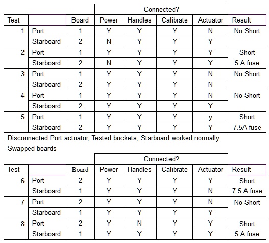
See updated test matrix below. It appears that the actuator itself is the culprit. Test 1-5 is last week. This week, I disconnected the port actuator and tested. The starboard bucket works. I’m still where I left off (nothing changed while I was gone).
I swapped boards, left the starboard actuator disconnected (it’s now being driven by the questionable board). Blew a fuse. (test 6)
I reconnected the starboard actuator (being driven by the questionable board) and disconnected the port actuator (being driven by the board that worked a few minutes ago). Starboard actuator calibrated and functioned normally. (test 7)
Chris said that the pots can be an issue, so I disconnected the green pot wire from the port board (couldn’t disconnect the two power wires because they’re driving the starboard signal as well). Blew a fuse (test 8)
The port actuator is the only thing that’s remained constant in all these tests, so I’m assuming that’s the culprit. So what do we do next? Timing is an issue (I’m so close, I want to get this running), unless the actuators are crazy expensive, I’d be willing to buy one to get it shipped to me quickly. I’ll use it to verify that the other one really is bad and return the bad one. At that point, you can issue a credit. As far as I’m concerned, the credit can sit on the books until I need parts in the future.
Do you have an alternative idea on this?
I appreciate all your help.
Answer:
We will try to get an actuator out on Monday. What shipping method do you want?
Last Thursday we got hit with 80mph straight-line wind which has caused considerable destruction. Most or much of Terre Haute is without power and it's rumored it could be many days before it will be restored. Consequently, many services are being disrupted such as shipping services but we will do our best.
These components are not tested by us when sold in kit form for obvious reasons so the possibility always exists that the components can be defective. The only way we can test these components is to set the whole system up which defeats the purpose of the craft being partially assembled!!
Sorry for all the inconvenience.
HI Chris,
No apologies necessary. This is what happens when you’re assembling & debugging equipment. I’m doing this in my garage on my schedule. I’ll take that over doing it in Taiwan with impatient customers over my shoulder (been in that situation, too).
As far as shipping, you need lights & someone to pick it up. Once you get things back on line, send it to me & let me know how it’s coming/tracking number so I can keep an eye out for it. Shipping method: whatever you think is best. I haven’t heard the latest if UPS is striking or not. I’d like to avoid getting caught up in that if possible.
Thanks again for your support and patience.
June 17, 2023
I finally got to the point of turning the key and debugging my hovercraft. Most looks good, but I’m stuck on the reverse system & need some help/insight.
General: I hooked up the battery & turned the key. All the smaller subsystems are working fine (lights, horn, navigation lights, all readings on gauges look reasonable/appropriate so I’m assuming they’re correct). I have not tried to start the motor yet. That will be last.
Here’s where I’m stuck (2 issues with the reverse thrusters):
I wired them per Form 17290 (12/3/2020) in the assembly manual. I referenced Form 16423 also and everything agreed (except a clear error in 16423. That form has the calibrate signal going to the shield connection). I checked them against the online wiring diagram and that also agrees (except for bullet/issue 2)
- When I flipped the switch to power up the reverse thrusters, the 15A fuse blew immediately. Disconnecting 12V and ground from both thruster boards made the fuse blowing go away, but there was still a short between board +12V and GND (measured with a multimeter). If I also disconnect the actuator Grn & Blue from those terminals, that goes away on the board. I disconnected the GRN & Blue wires from the board and Ohmed out those wires through the actuator itself. I get right around 20.5 Ohms on both of them. Is that normal? That is definitely low enough to blow a fuse. What do I do next?
- Pots on the handlebars: The online wiring diagram shows red & black wires from each pot going to the respective HND+ and HND- terminals on the boards. Both form 16423 & form 17290 show no connection to the Starboard HND+ or HND- terminals. The red & black wires are soldered together at the handlebars (so I’m assuming that the pots do not need to be isolated). Should I be running red & black wires from the Port HND+ & HND- terminals to the respective terminals on the Starboard board?
I’m thrilled to be at this point and am looking forward to resolving these issues & getting on to actually starting the motor. Then it’s final clean up and out to the lake. Any advice/suggestions you can give me to resolve these issues will be greatly appreciated.
Thank you
Answer:
The handlebar pots are wired as standard, I guess we could have made a mistake but for now, I will assume that the grey wire coming off the handlebar is correct.
You should check all the wires that are hooked up to the computer board. Check them two or three times and be certain everything is wired correctly. Perhaps a photo of the connections on each board sent to us would be a good move.
We can check this on Monday.
Glad you are in the home straight.
Thank you for the response so late on a weekend. Starting out as a 4 person business myself, I can relate to that.
Per your request, I’ve attached pictures of both boards. I’ll comment on them first and then comment on the issues. I believe you may have misunderstood my questions.
Starboard board:
The blue tape is on the red power wire so it wouldn’t short to ground as I was attempting to gather information on the issue. That was connected to the +12 terminal on the left.
The blue actuator wire was also on the +12 terminal on the left, but I disconnected that also in the debug process.
The white vehicle ground wire is disconnected off to the left. That was connected to the GND terminal on the left side of the board. Note: This wire was in the wiring kit for the reverse thrusters. I connected the ring lug of that wire to the ground (chassis) lug on the auxiliary board (mounted to the battery box).
The green actuator wire was also on the GND terminal on the left of the board.
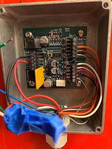
Also note here that there are no connections to HND+ or HND- terminals on this board (refer to this in item 2 below)
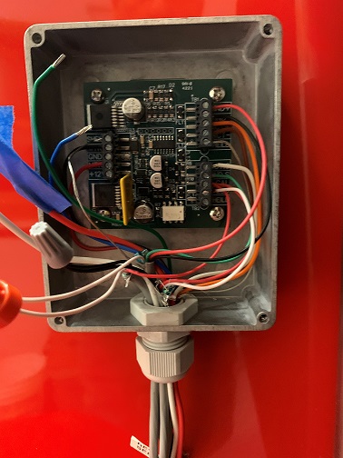
Port board:
The blue tape is on the red power wire so it wouldn’t short to ground as I was attempting to gather information on the issue. That was connected to the +12 terminal on the left.
The blue actuator wire was also on the +12 terminal on the left, but I disconnected that also in the debug process.
The white vehicle ground wire is disconnected off to the left. That was connected to the GND terminal on the left side of the board. Note: This wire was in the wiring kit for the reverse thrusters. I connected the ring lug of that wire to the ground (chassis) lug on the auxiliary board (mounted to the battery box).
The green actuator wire was also on the GND terminal on the left of the board.
The Grey wirenut connects the black LED wires that just pass through this box. I didn’t want to put a pigtail crimp on that wire until the system is debugged. (in case I had to replace a wire)
The orange wirenut connects the white pot wires that just pass through this box. I didn’t want to put a pigtail crimp on that wire until the system is debugged. (in case I had to replace a wire)
The issues
- 1. (the biggie) If the (4) disconnected wires in each box above are connected to the board, the fuse in the reverse thruster power line (under the dash) blows as soon as I turn the reverse thruster switch on. Because they share terminals, 12v power (red) wire and actuator blue are connected all the time. Similarly, the white chassis gnd and actuator green are connected all the time. I checked the resistance between actuator blue and actuator green when they’re not connected to anything (but the other wires are still connected per the pictures). They’re both 20.5 ohm (in parallel, that’s effectively like putting a 10.25 ohm resistor between power and ground). I checked my wiring against all 3 wiring diagrams referenced in my original email several times. If I resolve this issue, I’m ready to put fuel in it and see if the motor starts.
- 2. (less critical or a non-issue) I think you misunderstood my original question (second bullet, original email). I believe that the handlebar pots are wired correctly. My question is “Why isn’t anything wired to the starboard HND+ or HND- terminals?” Form 16423 & Form 17290 both say nothing is supposed to be wired to those terminals. The online diagram does show red and black wires from the pots going there, but the pots in that diagram are discrete. The pots on my vehicle share red and black at the handlebars. I’m wondering if the HND+ & HND- on the starboard board should be connected to something. If I didn’t have issue 1, I would have just started it up & see if the starboard bucket worked. But since I’m asking the other question anyway, I figured I’d toss this one in also.
Thanks again for your help through this process.
Answer:
This is Cliff from Neoteric Hovercraft. I measured ohm resistance on same actuator wires and got 20.8ohm and 21.0 ohms. So pretty close to the same. Another thing to look for when wiring up the boards; it is very easy to get one tiny little strand of wire to come out and cross over to other terminals. The guys in factory said go over it very carefully with a flashlight to check for little strands of wire. This could be causing shorting problem. Also to answer your other question, no there should not be wires hooked to starboard HND + or HND -
Thank you. Excellent advice. I’ll inspect all the connections this weekend. If there’s nothing obvious, I’ll go onto the checking each board in isolation and see if one of them are defective.
Test matrix/results
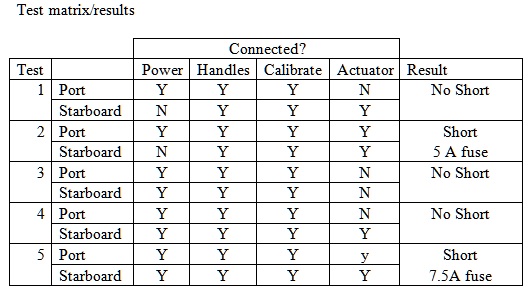
Notes:
- Tests 1 & 2 were run with 5A fuses. Tests 3-5 were run with 7.5 A fuse
- When I disconnected the actuator, I disconnected ALL the connections to that actuator, not just the power connections.
After Test 4 I calibrated the starboard bucket & it seemed to behave correctly. After calibration it seemed to work correctly.
After Test 5, I checked the starboard bucket & it’s still working fine.
Current state: Starboard fully connected and apparently operating correctly. Port side, Power and motor connections to the actuator disconnected from the board. Pot connections connected. +/- 12 V connected.
What do you think?
April 25, 2023
I’m making progress. Getting ready to install the reverse system.
A couple of questions.
See attached picture. Both buckets have what appears to be a stiffening strut from the top hinge down at an angle. However, it ends around ½” from the bucket itself. I can’t find what I’m supposed to do with that. Should I just use the adhesive/sealant and goop it up to keep it in place?
Answer:
WHEN THE BUCKETS ARE FITTED THE STAYS INSIDE EACH BUCKET ARE SHIMMED WITH WASHERS PROVIDED UNTIL PROPER ALIGNMENT IS ACHIEVED. MOVE THE STAY BACK AND FORTH UNTIL THE BEST FIT CAN BE FOUND THEN ADD THE SHIM WASHERS AND FINALLY, THE BOLT, LOCTITE THE NUT. THE STAY STIFFENS THE BUCKET.
The instructions for mounting the actuators say that there’s supposed to be marks on the body where to put the holes for the mounts. They’re not there.
Answer:
THE MARKS ARE THERE. SHINE A LIGHT ALONG THE BODY AND THE MARKS WILL STAND OUT. DRILL THE LOWER ONE AND FIT THE CLAMP WITH THE ACTUATOR INSTALLED. FIT THE CLEVIS TO THE BUCKET BELLCRANK AND MARK THE OUTLINE THE TOP OF THE CLAMP. REMOVE THE CLAMP AND ACTUATOR AND FIND THE CLAMP CENTERLINE. MEASURE DOWN FROM THE CLAMP TOP TO LOCATE THE UPPER BOLT HOLE, DO NOT USE THE MARK ON THE BODY TO DRILL THE TOP HOLE. DRILL HOLE AND FIT TWO 1/4 -20 X 3/4 IN LONG HEX SS BOLTS WITH WASHERS AND LOCTITE.
It seems to me that the centerline of the bracket should be right around 9½” from the bucket pivot rod (9.875” from the centerline of rotation of the bucket). And I put the clevis on the actuator & pinned it to the bucket rod. There’s about ½” of up/down slop in that assembly, so I can center the bracket in that range. Does that all sound right?
THIS ALL SOUNDS RIGHT AND THE INSTALLATION COULD BE UNDERTAKEN AS YOU DESCRIBE HOWEVER FOLLOW THE ABOVE DESCRIPTION AND NONE OF THESE MEASUREMENTS WILL BE NECESSARY.
And I noticed that the actuator rod moves in and out easily. I hope it’s supposed to do that when it’s not connected to anything.
Answer:
THE ACTUATOR HAS AN ELECTRICAL CLUTCH. WHEN THE CIRCUIT IS ENERGISED THE CLUTCH ENGAGES. YOUR ACTUATOR IS WORKING AS IT SHOULD.
As always, I appreciate your advice.
Thank you.
April 16, 2023
Have a few questions that I can use some help with:
Fuel system:
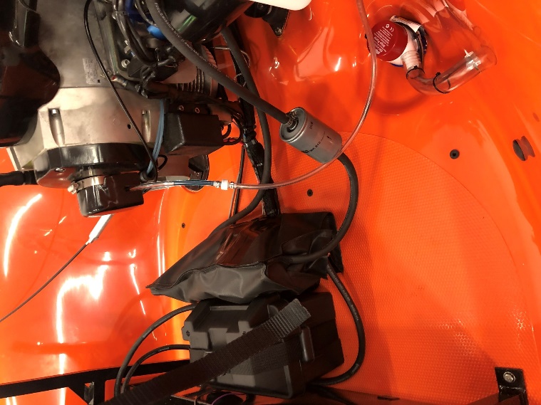
Note the extra potential connection at the top right of the picture. I expected that I’d just plug the fuel line (has a filter on it) into the bulb. But there’s this extra option. Should I just remove that filter on the corner of the tank and plug the line? Or am I supposed to connect something to it.
Is the sender switch polarity sensitive? It has a pink and black wire coming from it (visible in the picture). I would guess that pink is + and black is -, but I can’t find any documentation to confirm that. And am I going to hurt anything if I’m wrong?
Answer:
The filter on the port side of the tank is the tank vent. The filter is to prevent bugs from entering the tank. The fuel supply line is hooked up backward, you can see from the arrow on the filter that the way it's set up now the flow is in the wrong direction. It would have been set up right when we tested the engine.
The pink and black sender wire is not polarity sensitive but hook the black up to the ground. If the gauge goes in the wrong direction then flip the polarity but I don't think it will be necessary.
Kill switch wire to the engine:
The wire from the ignition switch and kill switch to the engine was in 2 pieces, but connected to the instrument panel when it came. But it was only held together with a wire nut (only wire nut in the whole harness). I changed that to crimp connectors, but want to make sure that there isn’t something else I’m supposed to be connecting that to or something. Or, because it is the only way to turn the engine off, am I supposed to be using a more robust connection (soldering & shrink wrapping for example)?
Answer:
The kill switch wire was held together with a wire nut for testing but it has to be separated for installation in the craft. It is also not polarity sensitive however if you get the wires mixed then it will either not stop the engine when the kill switch is pulled or you will not get a spark! The Crimp connector you used will work fine. The voltage on this kill wire is 75 Volt AC. You can also turn the engine off using the key switch.
Looking ahead:
Once I get the front seat installed and the reverse thrusters, I’m going to be closing in on starting this thing up. It said in the battery box installation section not to connect the battery until all circuits have been tested. I’m Ohming out what I can as I connect stuff and testing simple subsystems as I connect them (lights, for example). And I’m going to have to hook up the battery before I can test the reverse thrusters. What testing should I be thinking about doing between when I think the assembly is done and when I twist the ignition switch the first time?
Answer:
When the installation of all the wiring is complete just touch the positive battery lead to the positive battery post and if nothing is turned on there should not be a spark. If you get a spark then some investigation will be needed. Once there is no spark then tightly connect both battery leads and proceed to test each circuit. The reverse thrust computers are the most fragile components, they will not tolerate reverse polarity or voltage spikes. Voltage spikes can result from loose battery connections. There should be no battery connection to the engine electrical system but if the engine is jumped with reverse polarity it can ruin the engine CDI and coil.
Feb 16, 2023
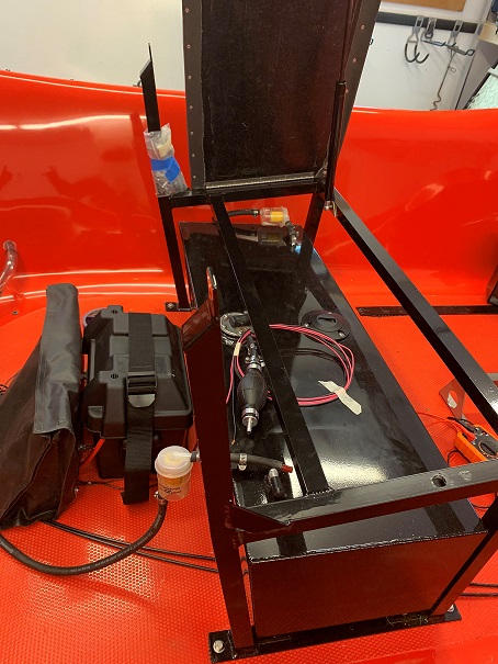
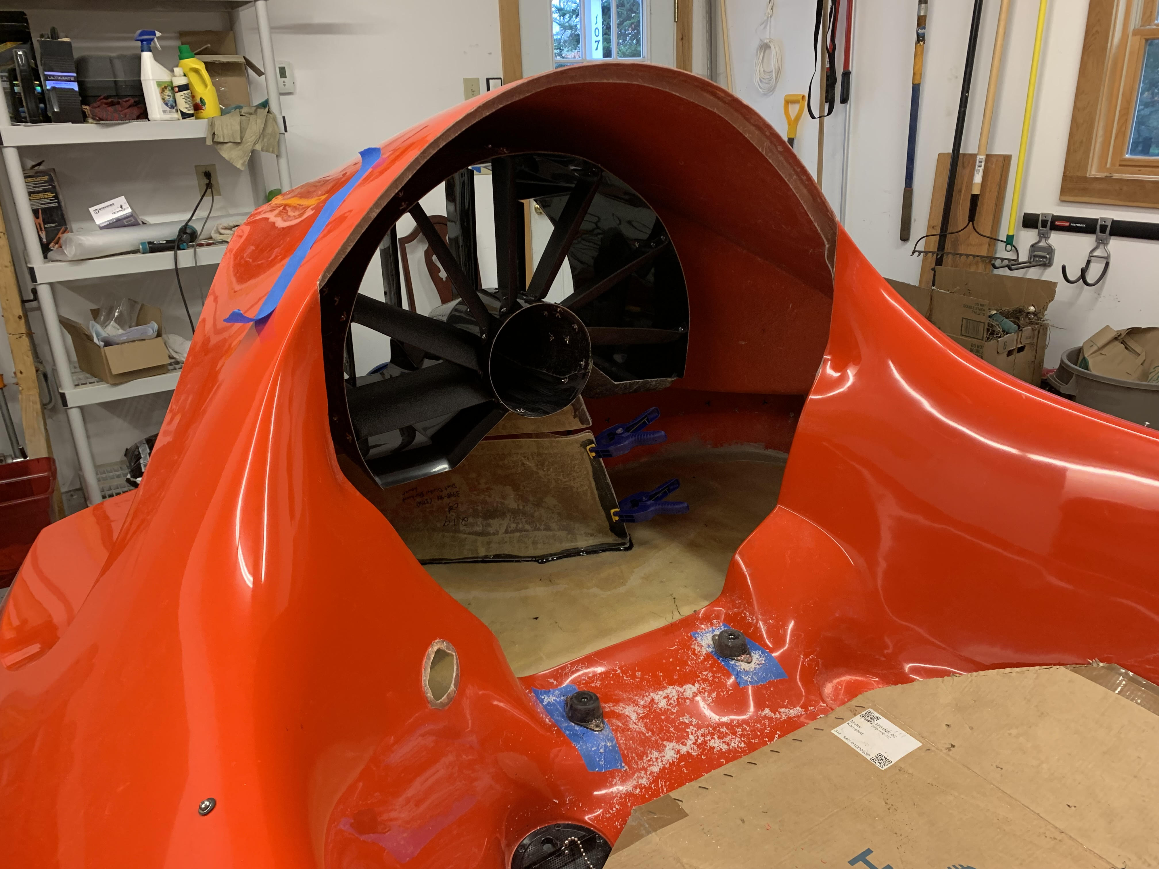
The engine and Dashboard are in. Wires are run through the body & reconnected to the auxiliary plate. Nav lights, horn, etc are wired and tested. I’m ready to take the next step. I was planning to install the battery & auxiliary plate, then the reverse system, then the seats and controls.
See picture below. Questions below relate to it,
Is that where the battery box and auxiliary plate go? The manual and video show attaching the auxiliary plate with bolts with nuts inside the battery box. It seems carriage bolts from the inside of the box with the nuts/washers on the outside would be easier and cleaner. Any issues with doing it that way?
Jan 22, 2023
I disassembled the mechanical assembly and put the foam in correctly. I’m now getting started on the wiring and need some help/advice/pointed in the right direction. If this is in the manual, I’m not finding it, so maybe just pointing me in the right direction is all I need.
I’m working on putting in the dashboard, wiring the lights, etc. right now. I’ll get to the reverse thrusters, rudder, etc. later. So these questions are focused on that, but I don’t know what I don’t know, so if anything’s suspicious, let me know that also.
Running the harness down the port side inside the air duct. I assume it’s supposed to go through the loop about ½ way down and again through the loop by the rudder (up high). Correct?
Answer:
THIS IS CORRECT: ALSO LOOP THE HARNESS ON TOP OF THE BILGE PUMP OUTLET HOSE INSIDE THE DUCT AND USE A PLASTIC TIE TO SECURE THE HARNESS TO THE HOSE.
I have a 40” piece of ¾” corrugated loom in a bag (part 3799-01). No clue where that goes, but I assume it has something to do with the harness I’m getting ready to put in. Where does that go?
Answer:
IF YOU HAVE A SIDE X SIDE KIT THIS LOOM IS TO COVER ALL THE CONTROL CABLES AND WIRE FROM THE HANDLEBAR BACK UNDER THE SEAT ACROSS THE FLOOR IN FRONT OF THE FUEL TANK AND BEHIND THE FRONT SEAT.
Dashboard install. Looks like well nuts go into the dashboard and screws from the outside. I’ll remove those and replace them later when I put the cabin or windshield on. Correct?
Answer:
THIS IS CORRECT THINKING.
I have 3 pieces of foam about ¾ x 3/8, one long and 2 only about 6” long. (Removable dash hardware kit #6665, includes 2 screws and 2 well nuts) Where does that go?
Answer:
THE LONG PIECE GOES ALONG THE TOP EDGE OF THE INSTRUMENT PANEL BETWEEN THE INSTRUMENT PANEL AND THE BODY. THE OTHER TWO PIECES GO ON EACH END OF THE PANEL AND ARE TRIMMED TO FIT. THE SCREWS GO ONE ON EACH SIDE THROUGH EACH END OF THE PANEL AND THE BODY.
Horn: Looks like that mounts INSIDE the air plenum port side in front of the dash. My arms BARELY fit through those holes to hold it in place. Any ideas/tricks to put that in?
Answer:
YOU NEED HELP FROM A PERSON WITH SKINNEY ARMS AND THE HORN IS MOUNTED INSIDE THE FRONT AIR DUCT WALL ON THE PORT SIDE FRONT. WHEN THIS IS RIVETED TO THE DUCT WALL THE US COAST GUARD CERTIFICATION PLATE IS RIVETED OVER THE RIVET HEADS INSIDE THE FRONT COCKPIT AND COVERS THE HORN RIVET HEADS.
Planning to use polyurethane sealant “Sikaflex” to bond the vibration mounts and the air duct dividers.
Hull label. Two of them, but only instructions on where to install one. And the post-it with it says Hull # US-NUS0855TE222, but only US-NUS0855 is engraved on them. What am I supposed to do with those? I have a laser engraver, so I can add the remaining characters if they’re supposed to be on there.
Answer:
YES, THE TE222 MUST BE ADDED TO THE HIN # PLATE. LOOKS LIKE WE FORGOT TO STAMP THESE!! BOND ONE PLATE INSIDE THE THRUST DUCT HIGH UP THE BODY ON THE STARBOARD SIDE, USE SIKAFLEX TO BOND. THIS IS THE SECRET NUMBER HIDING PLACE. THE REAL NUMBER IS BONDED AND RIVETED TO THE TRANSOM UNDER THE STARBOARD BUCKET AND ON THE OUTSIDE OF THE EXHAUST OUTLET. I THINK THE INSTRUCTIONS EXPLAIN THIS.
Jan 8, 2023
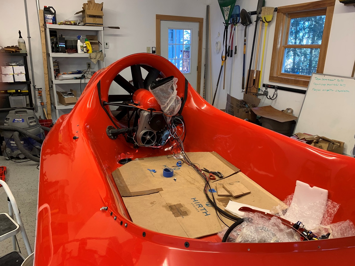
I had a few weekends to work on my hovercraft and make some nice progress.
I got the machinery module and muffler installed. It went quite smoothly. Everyone’s advice of "slow and methodical" worked well. You can see my whiteboard in the attached photo with the stuff that I don’t want to deal with now, but REALLY don’t want to forget later.
I did pick up a couple of things. The wellnuts to attach the exhaust flanges/dress brackets to the hull kept pulling out without expanding correctly. I figured that it must be because the bracket trying to compress the steel wool was pulling the wellnut out by the threads because there wasn’t enough pressure on the wellnut flanges to allow them to expand correctly. I tried putting fender washers (1/8 ID x ¾” OD) between the wellnut flange and the steel wool. Those put enough pressure in the flange to allow the wellnut to expand. Basically, I put a 1 inch 8-32 screw through the flange & steel wool, put on (3) fender washers & just started the wellnut. Then pushed the whole thing into the 5/16 holes I drilled in the hull and tightened the screws. This worked great. It compressed the wellnut without spacing the flange out too far to keep the steel wool from sealing.
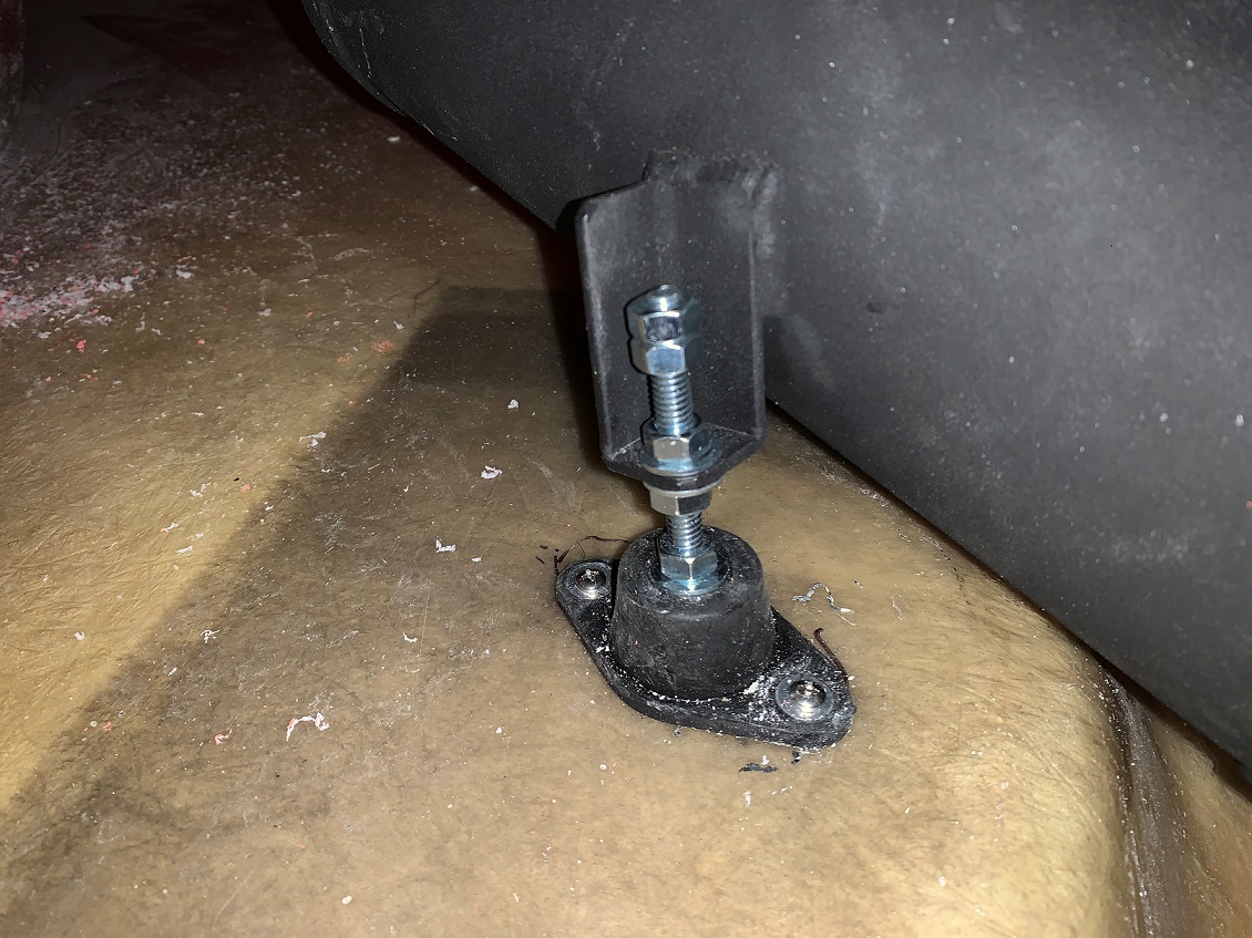
And: From the first photograph, you can see the adjustable mount I made for the muffler. I couldn’t figure out the spacer instruction in the assembly manual. I got a 5/16-18 threaded rod and some nuts and washers. This allowed me to adjust the muffler position to center it exactly in the center of the exhaust hole.
One product improvement that I would make: Drilling the wellnut holes for the exhaust flange was a pain. I had to locate through holes that were full of steel wool. If there was a template included with that kit it would be great.
Now on to the control system.
Sept 2022
I rebuilt the damaged during shipping rudder assembly. Thanks for everyone’s help.
Sanding the machinery module bell to get a good fit on the sides. I’m drilling all the way through the hull for the 4 machinery module vibration mount bolts.
Planning to use polyurethane sealant “Sikaflex” to bond the vibration mounts and the air duct dividers.
Have not had more than a few hours to work on it. The skirt strip is in place. I’m going to fit the motor during Thanksgiving time.
Finally got time to get back onto building my hovercraft. Body trimmed to fit the intake bell and the thrust duct is installed. Once Sikaflex dries on dividers I’ll finishing installing the machinery module. I’m not sure where all the foam pieces go but they appear to fit the machinery module. The long white "P" foam looks like it fits under the thrust duct rear mounting flange.